WELCOME TO REACON

- All
- Product Name
- Product Keyword
- Product Model
- Product Summary
- Product Description
- Multi Field Search
Views: 0 Author: Site Editor Publish Time: 2026-05-06 Origin: Site
The stakes of distribution network failures remain incredibly high for modern utility operators. Unplanned outages severely disrupt daily civilian life and halt critical industrial production. Furthermore, they damage expensive substation equipment and create serious public safety risks. Preventing these cascading failures requires robust protective hardware. However, engineers often struggle when balancing initial capital expenditures against long-term grid reliability. This guide transitions away from basic product definitions. It offers a strict, engineering-grade evaluation framework instead. We specifically target utility engineers, procurement managers, and system designers. You need compliance-aware, evidence-backed selection criteria to make highly informed purchasing decisions. By following this guide, you will learn exactly how to choose the right high voltage fuse cutout to protect your complex infrastructure effectively.
Proper selection requires aligning interrupting capacity and time-current curves with upstream/downstream cascading protection to prevent overstepping.
Material choice (Polymer vs. Alumina Ceramic) should be dictated by micro-climate data, not just unit cost.
Voltage ratings must account for creepage distances; a 36kV fuse cutout provides necessary arc flash mitigation in heavy industrial or long-distance transmission scenarios compared to 15kV units.
Adherence to IEEE C37.41 and IEC 60282-2 ensures component interoperability and mechanical reliability under stress.
Engineers must carefully match electrical parameters to physical grid realities. A simple calculation mismatch can cause devastating downstream grid consequences. You must treat these parameters as rigid boundaries rather than flexible suggestions.
First, you must understand the critical difference between system voltage and operating voltage. We follow a strict electrical engineering rule here. The rated voltage of the fuse must always exceed the maximum system operating voltage. You cannot simply match nominal numbers. For example, a 14.4kV distribution line operating at a peak of 15kV requires a protective device rated higher than 15kV to safely interrupt faults.
Next, calculating current ratings requires high precision. We rely on industry-standard sizing heuristics to establish a baseline. A common engineering rule of thumb helps size medium voltage circuits efficiently. You divide the transformer kVA capacity by 15 to find the baseline amp rating. For instance, a 1500kVA transformer typically demands a 100A rating. However, you must also apply thermal de-rating to this number. Ambient temperature extremes alter fuse performance significantly. Engineers apply standard adjustment coefficients. You must adjust the rating by ±10-15% for every 20°C variance from the baseline. Extreme heat causes premature melting, while extreme cold delays the trip. Factoring in local climate prevents nuisance tripping during severe summer heatwaves.
Finally, preventing overstepping remains critical for reliable distribution line protection. Overstepping happens when an upstream device blows before a downstream one. This forces an unnecessary truck roll to a remote substation instead of a local utility pole. You avoid this nightmare by applying a strict "2-3x margin" rule. The upstream link must handle two to three times the current of the downstream link. Proper time-current curve coordination guarantees this sequence. It ensures only the localized fault drops. This strategic isolation keeps the rest of the grid fully operational.
Selecting the correct voltage class involves much more than basic math. It requires analyzing your specific environmental conditions and infrastructure limitations. Different voltage classes directly dictate physical size and insulation capability.
Creepage distance and insulation play massive roles here. Higher voltage classes handle arc tracking much better in contaminated environments. Heavy air pollution, coastal salt spray, and industrial dust compromise standard insulation quickly. These contaminants form a conductive layer on the equipment. A 36kV fuse cutout provides extra creepage distance through deeper and more numerous insulation sheds. This longer surface path prevents electrical tracking and fatal arc flashes.
You must also carefully consider the physical footprint and installation constraints. Upgrading your voltage class fundamentally changes utility pole dynamics. A 36kV unit demands significantly more pole-mounting clearance. It requires robust structural support due to its increased size and heavier weight. Wind loading also increases. Linemen need more bucket truck space to maneuver these larger components safely during storm repairs.
Let us look at specific application scenarios. We break them down into two main operational categories:
15kV/22kV Scenarios: These units work perfectly for local municipal distribution grids. They handle light industrial step-down stations highly effectively. Their compact size suits crowded urban utility poles perfectly.
36kV Scenarios: Heavy industrial substations strictly demand this higher rating. Rural long-line transmission networks also require it. These harsh environments remain highly prone to unpredictable high-voltage transients. The extra insulation handles these sudden spikes safely.
Material science directly dictates the lifespan of your grid protection. Buyers must evaluate environmental micro-climates heavily before choosing an outdoor fuse cutout. We generally choose between two dominant insulator materials. Each offers very distinct operational advantages.
Porcelain, known industrially as alumina ceramic, represents the traditional choice.
Pros: Porcelain offers exceptional UV resistance. It features extremely high mechanical rigidity. We see incredible long-term chemical stability in urban environments. It rarely degrades under constant, decades-long sun exposure.
Cons: The material is very heavy. It becomes brittle under physical impact. Porcelain also remains highly susceptible to freeze-thaw cracking in extreme winter climates where moisture penetrates micro-pores.
Silicone polymer serves as the highly modern, engineered alternative.
Pros: Polymer delivers superior hydrophobic performance. It actively repels water and corrosive salt, forcing moisture to bead up and roll off. The material is lightweight and completely shatterproof. This makes it ideal for coastal areas or heavy-pollution zones.
Cons: It carries a marginally higher initial procurement cost. Low-grade silicone also shows potential for UV degradation over multi-decade spans. You must specify high-quality polymer to avoid premature fading and chalking.
We use a simple decision matrix to guide procurement teams. You must select based on historical site weather data and maintenance accessibility.
Environmental Factor | Recommended Material | Primary Justification |
|---|---|---|
Heavy Coastal Salt Spray | Silicone Polymer | Superior hydrophobic properties prevent severe arc tracking. |
High UV / Desert Heat | Alumina Ceramic | Impervious to solar degradation over multi-decade lifespans. |
High Seismic / Vandalism Risk | Silicone Polymer | Shatterproof design withstands heavy physical impacts. |
Extreme Freeze-Thaw Cycles | Silicone Polymer | Avoids the catastrophic micro-cracking common in porous ceramics. |
Understanding subtle mechanical nuances separates average buyers from expert procurement teams. The physical mechanism directly affects lineman safety, response times, and ongoing maintenance efficiency.
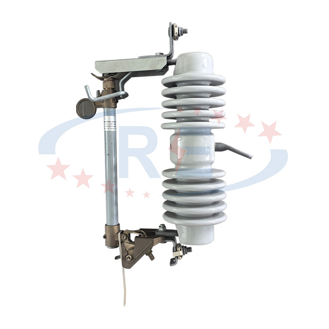
First, we must clarify industry terminology. Many professionals mistakenly confuse the mechanical action with the internal arc-quenching technology. A drop out fuse cutout refers strictly to the external mechanical hinge action. When the internal element melts, it releases a spring-loaded toggle. Gravity and spring tension pull the tube downward. This drop-out action provides a highly visible, reliable isolation break. Linemen can easily see the dropped tube from the ground. This visual confirmation is crucial for safety. The actual arc-quenching technology remains entirely separate. We use expulsion materials like boric acid or current-limiting quartz sand inside the tube to handle the electrical arc itself.
Hardware interoperability serves as another major evaluation factor. We strongly emphasize selecting units compatible with interchangeable Type-L fuse holders. Standardizing this specific component streamlines your inventory management drastically. Storms often destroy hundreds of cutouts simultaneously. Utilities need fast replacement capabilities using generic parts. You avoid stocking dozens of proprietary replacement parts by insisting on Type-L compatibility.
Component integrity dictates the mechanical lifespan of the unit. Engineers assess conductor materials very closely. Copper offers excellent conductivity but costs more. Aluminum reduces weight but has a lower melting point. We also inspect spring mechanisms carefully. They must use high-grade stainless steel. This ensures maintained contact pressure and excellent wear resistance. These springs endure hundreds of intense thermal expansion cycles over their long lifetime.
Modern utilities face increasing public scrutiny regarding environmental safety and operational responsibility. Your hardware choices now heavily influence corporate ESG metrics and community trust.
Wildfire hardening currently drives massive grid modernization efforts. Traditional open designs act as expulsion devices. They literally expel hot gases and vaporized molten debris outward to extinguish the arc. This directly ignites dry brush beneath utility poles. Modern non-venting or controlled-venting cutouts solve this massive problem. They contain the arc flash internally. This containment drastically reduces the expulsion of dangerous materials. It directly lowers wildfire ignition risks in vulnerable forestry regions.
Strict regulatory baselines also protect your infrastructure investment. You must mandate verified testing against global standards. Laboratories test these units by simulating thousands of amps to ensure the fiberglass tube does not explode. We use two primary benchmarks for equipment shortlisting:
IEEE C37.41 / C37.42: These outline strict North American performance and rigorous testing standards. They govern thermal limits, mechanical endurance, and safety margins.
IEC 60282-2: This standard defines international high-voltage testing requirements. It ensures safe arc interruption capabilities across diverse global power grids.
Even the absolute best hardware fails if installed poorly. Field execution matters just as much as strict procurement specifications. You must acknowledge field realities.
We routinely encounter several major installation pitfalls. Improper terminal torquing leads directly to loose connections and overheating. Linemen sometimes over-torque bolts out of fear, which cracks the ceramic base. Incorrect holder alignment causes frustrating false trips. Undersized fuse links blow prematurely during perfectly normal load fluctuations. Linemen must follow strict installation protocols to avoid these common, expensive errors.
In-rush current management requires special attention from system designers. Certain circuits support heavy motor loads or large magnetizing transformers. These heavy devices draw massive power upon initial startup. This temporary spike often reaches 6 to 10 times the normal operating current for a few seconds. We advise utilizing time-delay fuses for these specific circuits. These delayed links survive the temporary startup spikes without triggering a nuisance trip.
Finally, we must acknowledge inherent device limitations honestly. Drop-out mechanisms remain optimal for clearing gross overcurrents quickly. However, they consistently exhibit slow response times to low-level ground faults. A minor ground leak might not generate enough heat to melt the link quickly. You must deploy supplementary relay protection in critical substation nodes. This layered engineering approach covers the natural blind spots of mechanical drop-out systems.
Choosing the right protective hardware represents a delicate engineering balancing act. You must constantly weigh voltage class upgrades against physical pole constraints. You must leverage modern material science against historical local weather data. Most importantly, you must demand rigorous compliance with international safety testing standards.
Procurement teams should immediately adopt stricter vendor vetting practices. Always request certified third-party laboratory test reports. Evaluate the specific vendor warranty terms regarding UV degradation on polymers. Confirm hardware interoperability with your existing Type-L holders before committing to massive bulk purchases.
Your immediate next action should be a comprehensive system review. Encourage your team to thoroughly audit current grid protection schematics. Consult with a qualified application engineer to map out a site-specific hardware upgrade plan. Proactive planning today easily prevents catastrophic grid failures tomorrow.
A: Yes, upgrading the voltage class provides extra insulation and much longer creepage distance. This greatly reduces arc tracking in highly polluted or coastal areas. However, it requires verifying physical mounting space on the pole and acknowledging the higher unit cost. You must ensure your hardware structure handles the added weight safely.
A: "Expulsion" refers strictly to the arc-extinguishing method. It uses gas-evolving materials like boric acid to literally blow out the electrical arc. Meanwhile, "drop out" refers solely to the mechanical hinge action. This drops the tube downward to provide a visible safety break once the internal link blows.
A: Fuses are highly thermally sensitive devices. For extreme heat or cold, engineers must apply specific de-rating or up-rating percentages. You typically adjust the amp rating by 10-15% per 20°C shift from the 20°C baseline. This critical calculation prevents nuisance tripping in summer heat or dangerously delayed clearing during winter storms.