WELCOME TO REACON

- All
- Product Name
- Product Keyword
- Product Model
- Product Summary
- Product Description
- Multi Field Search
Views: 0 Author: Site Editor Publish Time: 2026-05-09 Origin: Site
Designing overhead power lines revolves around one central, uncompromising objective. Engineers must minimize physical equipment damage while successfully isolating localized faults. This delicate balance keeps any resulting outage radius as small as possible. You often deploy two distinct but completely complementary devices to achieve this critical goal. Think of one component as a heavy-duty shock absorber. It actively shields vulnerable transformers from massive, unpredictable grid voltage spikes. The other component acts strictly like an automated circuit breaker. It protects the broader grid from failed equipment by halting dangerous, sustained overcurrents.
Choosing, sizing, and positioning these hardware components correctly dictates overall system reliability. This alignment optimizes operational efficiency and ensures robust power distribution protection against severe environmental and electrical stressors. In this comprehensive engineering guide, we will explore their functional differences, evaluate core technical parameters, and review proven installation strategies. You will thoroughly learn how these essential components work together to defend your aging and modern electrical infrastructure alike.
Triggers Differ: A surge arrester activates during high-voltage transients (e.g., lightning), while a fuse cutout triggers during sustained overcurrent (e.g., short circuits).
Mechanism vs. Isolation: Arresters deflect voltage spikes to the ground without breaking the circuit; cutouts melt a physical link to safely isolate a fault, creating a visible air gap.
Synergy is Mandatory: Arresters provide primary lightning protection for transformers, but if an arrester fails and shorts to ground, the upstream fuse cutout must operate to prevent a feeder-wide outage.
Installation Hierarchy Matters: Mounting the arrester directly on the transformer tank (downstream of the cutout) limits the outage radius if the arrester fails.
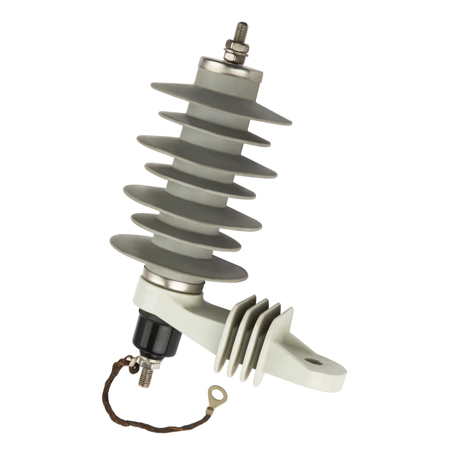
A modern zinc oxide arrester uses advanced Metal Oxide Varistors (MOVs) to manage unpredictable electrical energy efficiently. Manufacturers stack these specialized MOV blocks inside a weatherproof polymeric housing. They remain highly resistive under normal operating grid voltages. Normal electricity flows past them effortlessly without any leakage. However, a transient overvoltage event immediately changes this physical state. The internal impedance drops instantly during a massive lightning strike or a severe switching surge. This rapid internal shift shunts the destructive energy safely straight to the ground. Once the massive surge passes, the internal microstructure resets automatically back to a highly resistive state. It literally absorbs the shock and seamlessly prepares for the next weather event.
Conversely, the fuse cutout serves an entirely different yet equally critical purpose. It provides vital, heavy-duty overcurrent protection. Industry professionals consider it the primary series circuit breaker for overhead distribution lines. Its rugged anatomy features three main structural elements. You will find a heavy porcelain or polymer insulator body, a hollow fuse holder (often called a fuse tube), and a consumable fuse link inside. The internal tube often contains specialized ablative materials like bone fiber. When a dangerous current overload occurs, the thermal fuse link physically melts. This intense melting action vaporizes the ablative liner. The liner then expels specialized arc-quenching gases from the bottom of the tube. The sudden loss of mechanical tension causes the tube assembly to physically drop open. This mechanical action creates a highly visible, permanent disconnect indicator. Line crews can easily spot the hanging tube from the ground, ensuring they quickly identify the exact fault location.
Engineers must carefully evaluate several core dimensions when specifying overhead grid protection. These two components differ vastly in their specific trigger conditions, operational actions, and lifecycle management requirements. Understanding these technical dimensions ensures grid designers do not misapply technology. Applying the wrong component to a specific electrical threat leads directly to catastrophic equipment loss.
First, consider the primary triggering conditions. They react to completely different fundamental electrical forces. Arresters respond strictly to extreme microsecond voltage spikes measured in kilovolts (kV). These spikes happen incredibly fast, often in mere fractions of a microsecond. Cutouts react to sustained current overloads measured in amperes (Amps). These thermal overloads build up over milliseconds or even several seconds before reacting.
Second, look closely at their action type and system continuity profiles. You always install arresters in a parallel (shunt) configuration relative to the protected equipment. They clamp the severe voltage spike while maintaining steady, uninterrupted power flow to downstream residential or commercial users. You strictly install cutouts in a series configuration along the overhead line. They must completely interrupt and break the circuit to stop the fault current from causing electrical fires or equipment meltdowns.
Third, examine their lifecycle lifespan and reusability expectations. Manufacturers design surge devices to handle dozens of transient events over their operational lifecycle. They require no manual replacement unless an extremely violent event directly exceeds their maximum thermal energy absorption capacity. Cutouts behave quite differently in the field. They demand immediate physical intervention after a single protective operation. A qualified lineman must manually replace the melted fuse link using an insulated fiberglass hot stick before restoring power.
Finally, failure modes differ significantly between the two technologies. An overloaded polymeric surge arrester typically features a built-in mechanical safety mechanism. It will often detonate and blow off its ground lead disconnect upon experiencing a catastrophic internal failure. This intentional, explosive separation physically clears the wire and prevents a permanent line-to-ground fault.
Protection Dimension | Surge Arrester | Fuse Cutout |
|---|---|---|
Triggering Condition | Voltage spikes (kV) occurring in microseconds | Current overloads (Amps) building in milliseconds |
Action Mechanism | Parallel shunt to ground (Clamping overvoltage) | Series circuit interruption (Physical isolation) |
System Continuity | Maintains continuous power flow during operation | Breaks the circuit completely and stops power flow |
Reusability | Automatic reset functionality for multiple events | Requires manual fuse link replacement after one use |
Grid resilience relies heavily on exactly how these separate components interact during catastrophic field events. They form an active, highly coordinated defensive layer when installed correctly on a distribution pole framework.
The first line of defense typically involves severe weather events traversing the overhead lines. Imagine a massive, direct lightning strike hitting a bare overhead conductor. The transient wave travels rapidly down the line toward the local distribution transformer. The arrester instantly recognizes and absorbs this massive transient overvoltage. It rapidly shunts the dangerous energy safely into the earth via the grounding wire. This rapid diversion prevents the fragile transformer windings from suffering catastrophic insulation breakdown. The nearby fuse cutout remains completely unaffected during this exact moment. The microsecond duration of a lightning strike proves far too short to heat and melt the heavy thermal link.
However, extreme grid anomalies demand a robust, guaranteed failsafe sequence. Sometimes a severe surge significantly exceeds the maximum thermal energy absorption limit of the internal MOV blocks. When this violent destruction occurs, a specific, predictable sequence must unfold to save the larger grid architecture.
The internal MOV blocks overheat, permanently degrade, and structurally fail under the immense stress.
This internal catastrophic failure transforms the device into a permanent dead short directly to the ground.
The upstream fuse cutout immediately detects this newly created massive fault current rushing toward the earth.
The thermal fuse link inside the tube melts rapidly due to the intense, sustained overcurrent.
The internal gases extinguish the arc, and the heavy fuse tube drops open, visually isolating the compromised segment.
This integrated failsafe sequence provides massive operational decision value for regional grid operators. Without the upstream cutout acting as a strict boundary, a failed and shorted protection device would quickly trigger the main substation feeder breaker. That disastrous scenario takes down an entire distribution line, plunging thousands of homes into darkness. The proper coordination ensures only one specific transformer drops offline instead, isolating the damage perfectly.
Engineers and utility managers frequently debate the exact placement of these devices on the distribution pole framework. You must carefully consider where to logically place the clamping device relative to the isolation fuse.
Industry best practice today strongly favors downstream mounting configurations. You physically mount the arrester directly onto the transformer tank, positioned electrically after the cutout. This arrangement strictly ensures the absolute shortest possible lead length connecting the protective device to the transformer bushing. Minimizing lead length directly reduces dangerous inductive voltage drops during a fast-rising surge. Even an extra three feet of connecting wire can add thousands of volts to the equipment due to rapid induction. This close physical proximity maximizes the overall lightning protection efficacy for the highly vulnerable transformer windings.
Downstream mounting also delivers tremendous, practical troubleshooting benefits for field maintenance crews. If the clamping device catastrophically shorts to ground due to a massive strike, only that specific transformer’s individual cutout blows. This deliberate action creates a highly localized, single-point power outage. Dispatched linemen can easily drive down rural roads, visually spot the dropped open fuse tube, and locate the exact fault instantly without patrolling miles of line.
Conversely, upstream mounting introduces significant, unnecessary operational risks. Some older legacy designs placed the overvoltage protection device before the isolation fuse. Placing it upstream means a catastrophic internal short cannot physically trigger the local cutout mechanism. Instead, the resulting massive fault current travels continuously back up the main line. It will eventually trip an upstream hydraulic recloser or even a large substation breaker. This poor configuration unnecessarily widens the outage radius dramatically. It plunges dozens or hundreds of customers into darkness. It also deeply complicates the fault location process, forcing crews to comprehensively inspect the entire primary line.
Proper procurement methodologies require far more than just picking standard parts from a vendor catalog. You must actively coordinate their operational characteristics to ensure seamless field performance.
Sizing and coordination form the absolute foundation of long-term grid reliability. You must rigorously ensure the specific fuse link rating properly aligns with expected system demands. Field engineers typically specify either fast-acting K-type or slow-acting T-type links depending on the regional load profile. You must explicitly coordinate this thermal rating against the known let-through energy of the chosen protection device. Improper electrical sizing frequently leads to frustrating nuisance blowing. A relatively normal, harmless surge event might prematurely melt a poorly specified, excessively sensitive fuse link, causing an unnecessary truck roll.
Many utility companies now critically evaluate the business case for adopting integrated combo units. These specialized assemblies seamlessly combine both essential devices onto a single, pre-engineered mounting bracket.
Pros: A well-designed combo unit significantly reduces visual pole clutter. It inherently lowers difficult installation time for bucket truck crews. It also streamlines your internal procurement processes and deeply simplifies utility inventory management over time.
Cons: Combo units inherently offer slightly less spatial flexibility during complex installations. If a specific wooden crossarm presents highly unique physical constraints, linemen might strongly prefer the adaptability of separate mounting brackets.
Furthermore, no surge arrester functions optimally without a verified, robust, low-impedance ground path. You absolutely cannot ignore this critical physical installation requirement. A poor, highly resistive ground connection severely limits necessary energy dissipation during a strike. It aggressively increases the risk of localized ground potential rise (GPR). High GPR can quickly damage nearby sensitive consumer electronics and seriously threaten human safety near the pole base. Engineering teams must strictly adhere to established IEEE and IEC grounding guidelines. Proper soil resistivity testing and adequate copper ground rod driving remain absolute non-negotiable steps during any new pole installation.
You must clearly recognize that these crucial grid components are never mechanically or electrically interchangeable. They function strictly as highly interdependent layers of comprehensive network protection. They work cooperatively every single day to maintain global grid stability and isolate severe localized damage efficiently.
When planning your next major infrastructure upgrade or rural expansion, keep these critical action steps firmly in mind:
Evaluate regional fault current levels accurately before selecting specific thermal fuse links for your network.
Verify local soil resistivity and physical grounding conditions to guarantee optimal energy dissipation during severe weather patterns.
Assess your local maintenance resources and pole space constraints when choosing between standalone components or integrated combo units.
Always strongly prioritize downstream mounting configurations to restrict outage radiuses and protect vital transformers optimally.
Implementing these proven engineering strategies strictly protects costly, hard-to-replace transformers and vastly improves customer uptime metrics. Consistent adherence to modern engineering standards actively builds maximum grid resilience against highly unpredictable environmental and electrical threats.
A: No. They perform fundamentally different functions. Arresters cannot safely isolate sustained overcurrents or typical short circuits. Conversely, cutouts cannot react fast enough to block microsecond voltage spikes caused by lightning strikes. You need both to protect the overhead grid adequately.
A: A blown cutout provides an obvious visual cue. Its internal fuse tube will hang vertically down from the main bracket. A failed modern arrester will typically have its ground lead disconnector completely blown off. You might also spot visible cracking or severe charring on its exterior polymeric housing.
A: No, provided they are manufactured to strict structural and electrical standards. They simply share a common mounting bracket and a unified insulator structure. This efficient physical arrangement perfectly preserves the independent electrical functionality of both the internal varistor blocks and the isolation fuse.