WELCOME TO REACON
- All
- Product Name
- Product Keyword
- Product Model
- Product Summary
- Product Description
- Multi Field Search
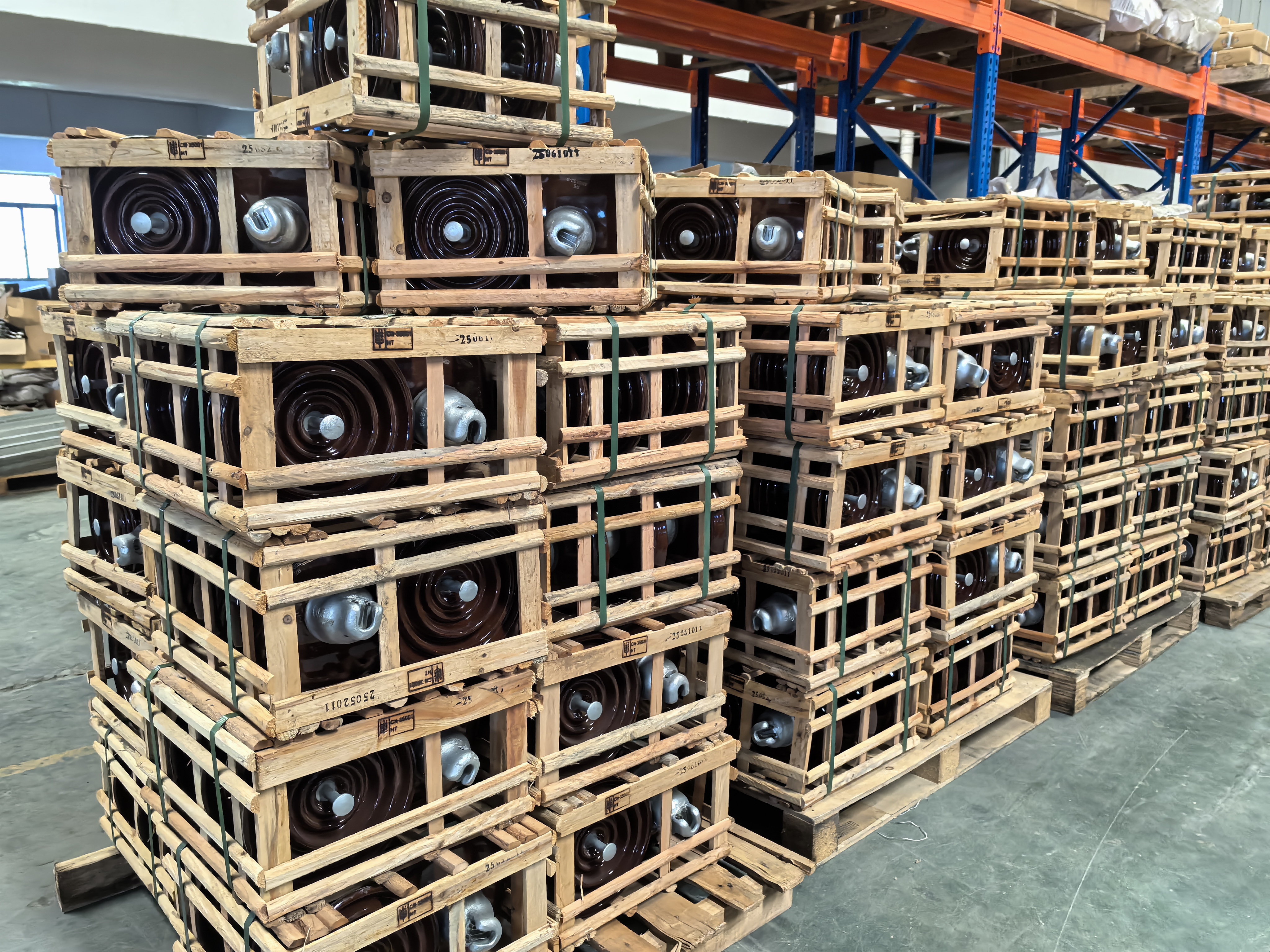
Porcelain insulators are insulators made of electrical ceramics as insulation components. Electrical ceramics are baked from quartz, feldspar, and clay as raw materials. The surface of porcelain insulators is usually covered with porcelain glaze to improve their mechanical strength, prevent water infiltration, and increase surface smoothness.
| Availability: | |
|---|---|
| Quantity: | |
Porcelain insulators are insulators made of electrical ceramics as insulation components. Electrical ceramics are baked from quartz, feldspar, and clay as raw materials. The surface of porcelain insulators is usually covered with porcelain glaze to improve their mechanical strength, prevent water infiltration, and increase surface smoothness.
Features:
1.High thermal conductivity
2.The highest thermal shock resistance in ceramics
3.Has good chemical and thermal stability
4.Strong anti-aging ability
5.Flexible assembly
Our advantages:
1.More environmentally friendly: It is made from natural materials through simple mixing and curing; It can be stored together with other waste in a garbage dump. It can be used as a recycled material for the production of ceramics and similar products.
2.Compared to polymer insulators, they have higher electrical strength and longer service life in terms of loads generated by charges and other temporary electrical phenomena.
3.Our ceramic insulators have high heat resistance and strength, can withstand temperatures up to 1000 ℃, and have significantly higher resistance to surface degradation.
4.Ceramics can resist rodents, termites, birds, and other animals that can damage the integrity of polymers.
5.Strong corrosion resistance in acidic and corrosive environments.
6.Ceramic materials can provide very high mechanical strength under pressure and hardness: ceramic insulators do not deform unless external forces are applied. It can guarantee a service life of up to 40 years.


Parameter
ANSI Class | 52-1 | 52-2 | 52-3 | 52-4 | 52-5 | 52-6 | 52-8 | 52-9 | 52-10 | ||
IEC Class | XP-45C | XP-70C | XP-70 | XP-70C | XP-110 | XP-110C | XP-160 | XP-45C | XP-160C | ||
Fig No. | 1 | 2 | 3 | 4 | 3 | 4 | 3 | 5 | 4 | ||
Main DemensionS/MM | (H)Unit Spacing/MM | 140 | 160 | 155 | |||||||
(D)Disc Diameter/MM | 165 | 190.5 | 254 | 254 | 254 | 254 | 254 | 108 | 280 | ||
Leakage Distance/MM | 178 | 210 | 292 | 292 | 292 | 292 | 320 | 171 | 280 | ||
Power-frequency Punc- | 80 | 90 | 110 | 110 | 110 | 110 | 110 | 80 | 110 | ||
Average Flashover Voltage | Power Frequency | Dry/KV | 60 | 65 | 80 | 80 | 80 | 80 | 80 | 80 | 80 |
Wet/KV | 30 | 35 | 50 | 50 | 50 | 50 | 50 | 30 | 50 | ||
Critical Impulse | Positive/KV | 100 | 115 | 125 | 125 | 125 | 125 | 125 | 125 | 100 | |
Negative/KV | 100 | 115 | 130 | 130 | 130 | 130 | 130 | 90 | 130 | ||
Combined M &E Strength/KN | 45 | 70 | 70 | 70 | 111 | 111 | 160 | 45 | 160 | ||
Impact Failing Load/N M | 5 | 6 | 6 | 6 | 7 | 7 | 10 | 5 | 10 | ||
Routine Tension Load/KN | 22 | 35.5 | 35.5 | 35.5 | 55.5 | 55.5 | 80 | 22 | 80 | ||
R.I.V Date | Test Voltage To Ground/KV | 7.5 | 7.5 | 10 | 10 | 10 | 10 | 10 | 7.5 | 10 | |
Max R.I.V at 1000KHZ/μV | 50 | 50 | 50 | 50 | 50 | 50 | 50 | 50 | 50 | ||
Weight/KG | 2.5 | 3.9 | 4.6 | 4.9 | 5.6 | 5.9 | 6.9 | 2.6 | 7.2 | ||
